CONDENSER
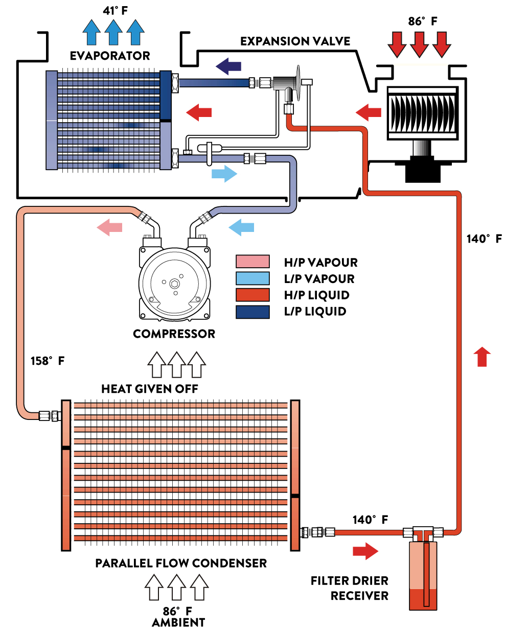
The condenser function is to act as a heat exchanger and allow heat to flow from the hot refrigerant to the cooler outside air. R134a entering the condenser will be a high-pressure high temperature vapor. As the R134a vapor travels through the tubes of the condenser heat is given off to the cooler ambient air; the refrigerant vapor condenses and changes to a liquid state. At this point a large amount of heat is given off by the R134a. The refrigerant will now be a hot, high pressure liquid.
PARALLEL FLOW CONDENSER SYSTEM
The function of a condenser is to act as a heat exchanger and allow heat tot flow from the hot refrigerant to the cooler outside air. R134a entering the condenser will be high pressure, high temperature vapor. As the R134a vapor travels through the tubes of the condenser, heat is given off to the cooler ambient air; the refrigerant vapor condenses and changes to a liquid state. At this point, a large amount of heat is given off by the R134a. The refrigerant will now be a hot, high pressure liquid.
PARALLEL FLOW DESIGN:
(recommended for R134a) This design is very similar to a cross flow radiator. Instead of refrigerant traveling through one passage, it can now travel across numerous passages. This will give larger surface area for the cooler ambient air to contact.
R134A – R12 COMPARISON:
As R134a operates on higher pressures, less internal flow, restrictive and improved heat rejection condensers are required. Most manufacturers select the parallel flow design for this version. They are approximately 25% more efficient than the serpentine condensers.
CONDENSER ELECTRIC FAN:
Most vehicles with air conditioning require an electric fan to assist air flow, either pushing or pulling the air through the condenser, depending on which side of the condenser the fan is placed. The majority of vehicles using R134a require this additional condenser cooling due to the higher operating pressures of R134a. Also, some vehicles have smaller grills or bumper bar openings. This causes poor air flow conditions by the amount of air flow over the condenser. The condenser fan is operator with a/c engaged in various ways:
· medium pressure switch
· indirect connection to the compressor clutch
· via the electronic control module (ECM)
· signal from the a/c switch activation


SERPENTINE
This type of condenser consists of one long tube which is coiled over and back on itself with cooling fins in between the tubes.


PARALLEL FLOW:
This design is very similar to a cross flow radiator. Instead of refrigerant traveling through one passage (like serpentine type), it can now travel across numerous passages. This will give larger surface area for the cooler ambient air to contact. Must be mounted where hose can reach.


CONDENSER FAN CONTROL
MEDIUM PRESSURE: Used to engage the condenser fan at a predetermined refrigerant pressure.
Example: Condenser fan high speed activation at 1770kPa refrigerant pressure.
These switches can be individual or a combination of the two or even three pressure ranges.


CONDENSER MOUNTING
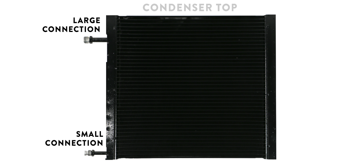
Condenser must be mounted within 1″ of radiator without touching. Failure to do so will prevent the A/C System from functioning correctly. Refrigerant flows from the compressor to the top connection of the condenser down to the bottom connection. This allows the refrigerant to change from gas from to a liquid from needed for the system to operate. We also recommend that the condenser is about an inch away from the radiator. Must be mounted where hoses can reach.


LARGE CONNECTIONS: top of condenser
SMALL CONNECTIONS: bottom of condenser
Early condenser design used round copper tubes with 1 or 2 passes and R-12 as refrigerant. The size of the R-12 and 22 molecules as well as their ability to collect heat and then release heat allowed the a/c condenser to be laid down flat and function effectively. There were few problems with ‘oil sumping’ e.g. the retention of oil in the condenser and no problems with poor heat transfer away from the system with proper air flow across the condenser.
But modern parallel flow condensers use a vertical manifold or a large tube on the ends that receive the refrigerant from the compressor and distributes it across the core in smaller tubes dissected by heat exchanging fins. The refrigerant and oil pass through the condenser returning to the vehicle to absorb more heat and then to the compressor to lubricate and cool it.
Because of this design of multi-flow condensers illustrates why you cannot you lay down parallel flow condenser flat or parallel to the ground. The oil within the system is heavier and thicker than refrigerant gas the gas separates leaving the oil trapped in the condenser. The refrigerant continues this cycle depositing the oil in the compressor and ultimately starving the compressor of lubrication.
Compessors can survive a slightly angled mounting but totally parallel a/c condensers coupled with high ambient temperatures and high usage hours will contribute to premature compressor failure.
REMINDER
Use two wrenches to tighten O-ring fittings. The video below will explain the importance.
CONDENSER TROUBLESHOOTING
TESTING CONDENSER AIR FLOW
1. Place a piece of paper on the condenser with the car in idle and see if the paper is held in place.
2. With the car in idle, attach gauges and place a large capacity fan in front of the condenser. What happens to the pressures?
3. With car still in idle and gauges attached, pour water down the front of the condenser. What happens to the pressures? If the paper is held in place, you are at least getting some air flow. If the high side decreases during test 2 & 3, then your condenser is not getting enough air which is causing your system to not cool properly. To correct this issue, you will need a more powerful mechanical fan.
CONDENSER DOES NOT DISSIPATE ENOUGH HEAT
CAUSE: Air flow blocked by dirt accumulated on the heat exchangers; water radiator/condenser
SOLUTION: clean the radiator and condenser thoroughly
CAUSE: The pressure switch or water temperature bulb are not tripped at the correct pressure and temperature levels
SOLUTION: cut out the controls using the appropriate electrical connection
CAUSE: Electric fan does not work
SOLUTION: Power the electric fan directly. Replace if it still does not work.
CAUSE: Incorrect functioning by the electric fan (incorrect rotation direction)
SOLUTION: fan must be “suction” type when placed between the heat exchangers and the engine, the “blowing” type if placed between the heat exchangers and the outside air intake
CAUSE: Condenser is not positioned correctly
SOLUTION: make sure that the distance between the radiator and condenser is 15-20mm
CAUSE: Engine water overheated
SOLUTION: replace the defective part if necessary. Make sure the original engine cooling system is working properly
